SPATIAL DATABASES

|
|
SPATIAL DATABASES |
|
UML is a visual modeling language of general purpose. The UML combines certain number of graphical elements into diagrams. Because it is a language, the UML has rules for combining these elements. UML consists of nine basic diagrams, where UML class diagrams (Object Management Group 2003) are the mainstay of object-oriented analysis and design. UML class diagrams show the classes of the system, their interrelationships (including inheritance, aggregation, and association), and the operations and attributes of the classes. Class diagrams are used for a wide variety of purposes, including both conceptual/domain modeling and detailed design modeling.
Main components of a UML class diagram are:
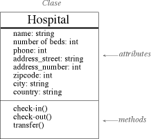
Classes are typically modeled as rectangles with three sections: the top section for the name of the class, the middle section for the attributes of the class, and the bottom section for the methods of the class. Attributes are the information stored about an object (or at least information temporarily maintained about an object), while methods are the things an object or class do. For example, a class hospital has attributes such as name, number of beds and address. Hospitals also check-in patient, check-out patient, and transfer patient. Those are all examples of the things that happen at a hospital, which get implemented (coded) as methods.
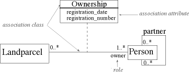
Objects are often associated with, or related to, other objects. When you model associations in UML class diagrams, you show them as a thin line connecting two classes. Associations can become quite complex; consequently, you can depict some things about them on your diagrams. The label, which is optional, although highly recommended, is typically one or two words describing the association. Multiplicity of an association is the degree in which each class participates in the association. The multiplicity of the association is labeled on either end of the line, one multiplicity indicator for each direction:
Symbol Description 0..1 Zero or one 1 One only 0..* Zero or more 1..* One or more n Only n, where n > 1 0..n Zero to n, where n > 1 1..n One to n, where n > 1 Another option for associations is to indicate the direction in which the label should be read. This is depicted using an arrow, called a direction indicator. Direction indicators should be used whenever it isn't clear which way a label should be read. My advice, however, is if your label is not clear, then you should consider rewording it. The arrowheads on the end of the line indicate the directionality of the association. A line with one arrowhead is uni-directional whereas a line with either zero or two arrowheads is bidirectional. Officially you should include both arrowheads for bi-directional assocations, however, common practice is to drop them. At each end of the association, the role, the context an object takes within the association, may also be indicated. This indication may be used only in cases when it isn't clear from the association label what the roles are, if there is a recursive association, or if there are several associations between two classes.
|
|
|